Mini Relay 4 Pin Micro Relay Wiring Diagram

Wiring Diagram 4 Pin Relay Fitfathers Me Fancy At Relay Wiring Diagram 4 Pin Relay Electrical Circuit Diagram Automotive Electrical

Micro Mini And Pcb Relays
12 Volt Car Relays Used In Automotive Industry
Diy Bussmann Rtmr Fuse Block Part 4 Wiring And Schematics Bodenzord
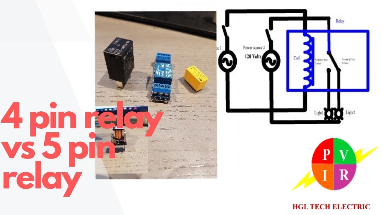
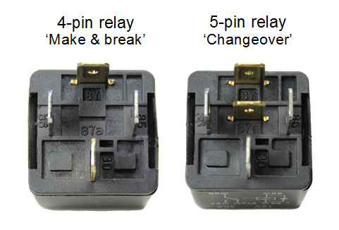
4 Pin Relay Vs 5 Pin Relay 4 Pin Relay And 5 Pin Relay Wiring Diagram 5 Pin Relay Wiring Youtube
Automotive Relay Guide 12 Volt Planet
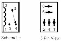
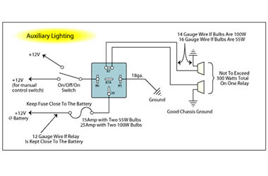
An iso micro relay has the control circuit connected to pin 86 and pin 85 and the load circuit connected to pin 30 and pin 87 or 87a.
Mini relay 4 pin micro relay wiring diagram.

Bosch 4 Pin Relay Wiring Diagram For Doorbell Symbols Car Relay Diagram Electrical Wiring Diagram

4 Pin 12v 20amp Automotive Micro Relay Make And Break Car Van Bike Y1 Ebay

Usb Wire Diagram Schematic Micro Wiring Connector Colors To With Volovets Info In 2020 Electrical Diagram Circuit Diagram Automotive Electrical

Diagram By Akita Your Diagram Source From Akita Automotive Electrical Relay Automotive Mechanic

Ww 2737 12v Normally Closed Relay Wiring Diagram Schematic Wiring

4 Pin Relay Wiring Diagram Lights Relay Car Horn Automotive Electrical
Relay Case How To Use Relays And Why You Need Them Onallcylinders

4 Pin Relay Diagram 4 Pin Relay Wiring 4 Pin Relay Animation 4 Pin Relay Connection Youtube

5 Pin Relay Wiring Diagram Electrical Circuit Diagram Electrical Diagram Trailer Wiring Diagram

5 Pin Relay Wiring Diagram 2 Pretty Narva 12v Relay Wiring Diagram 5 Pin Best Of In 5 Pin Relay Wiring Diagram Electrical Diagram Relay Automotive Electrical

Best Relay Wiring Diagram 5 Pin Wiring Electrical Circuit Diagram Electrical Diagram Trailer Wiring Diagram

Nz 9241 12 Volt Relay With Resistor Free Diagram

Astounding 5 Pin Relay Wiring Diagram Driving Lights Along With Wiring Diagram For Driving Light Relay Automotive Electrical Automotive Repair Electricity
Should I Use A Relay For Fuel Pump The H A M B

Denso 4 Pin Relay Diagram

Image Result For 4 Pin Relay Wiring Diagram Horn Electrical Wiring Diagram Electrical Circuit Diagram Diagram
12v 20 30a 87a 5 Pin Normally Open Relay Oem 4rd 003 520 08 Micro

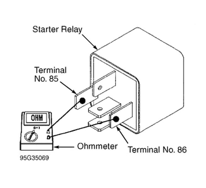
How To Test A Four Terminal Relay 7 Steps With Pictures
Https Encrypted Tbn0 Gstatic Com Images Q Tbn 3aand9gcskg4tzz6bu9gccakuyezuepajxpiuxalcxdf4diyreq3c Udap Usqp Cau
Https Www Consulab Com Files Electricaldshandoutv20181r1reduced Pdf

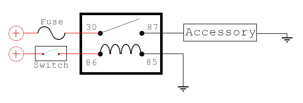
Wrg 9159 Accessories Relay Wire Diagram

Nilight 5 Pack Relay Socket Kit Relay With 30a Fuse And Switch Harness Nilight Led Light

Aux Light Wiring Diagram 5 Wire Relay Electrical Wiring Diagram Trailer Light Wiring Automotive Electrical

Beautiful 12 Volt Relay Wiring Diagram Symbols Diagrams Digramssample Diagramimages Wiringdiagramsample Wiringdiagram Diagram Wire Relay
Source : pinterest.com
